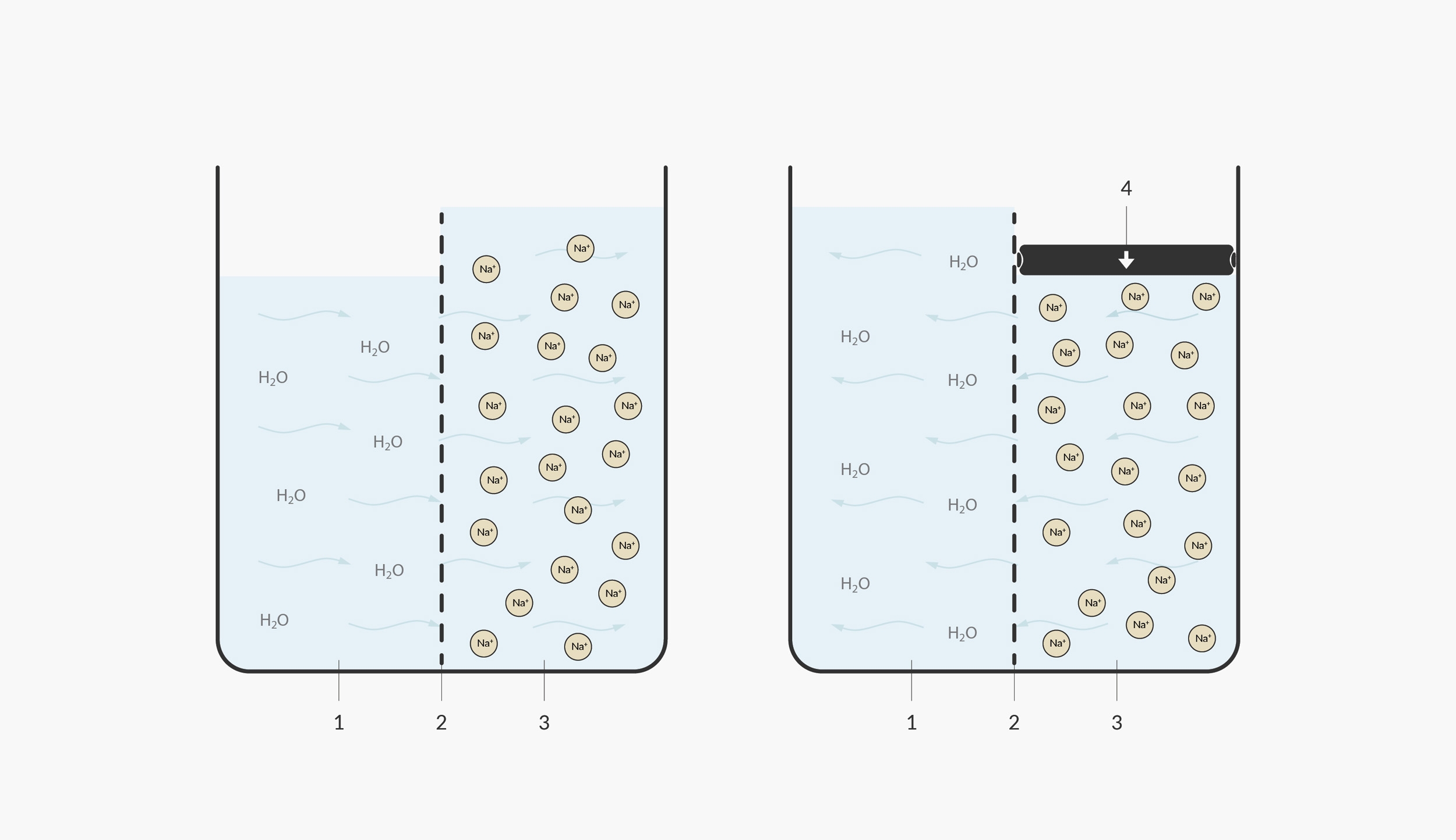
 In this illustration, we model the natural osmosis on the left and reverse osmosis on the right. 1. under saturated/pure water 2. semi-permeable membrane 3. saturated salt water 4. pressure
In nature, hard water wouldn’t travel through a fine membrane; the opposite would normally occur. Pure water normally attempts to travel towards hard water to dilute it. An example of the process occurs in nature when a tree is affected by salinisation. If a tree’s roots encounter salt water, the water inside the tree naturally osmose (move to an area of higher concentration)—out of the roots and into the salty water, in the attempt to dilute the saltiness of the surrounding water.
In order to ‘reverse’ the process of osmosis, a pump is required to get the water moving in the opposite direction. Reverse osmosis machines use a strong diaphragm pump, which normally operates at as high as 6 bars of pressure.
RO systems pump water through an osmosis membrane. RO systems work differently from the way cartridges, designed to hold sediment and carbon filters, do. Here is a diagram of a reverse osmosis membrane. A section has been unrolled to show you what the spiral of rolled-up layers are made from. Each layer has a narrow space on either side that allows product water to travel towards the centre of the spiral. There, it collects in the permeate collection tube and is piped off towards the blending valve.
Wastage
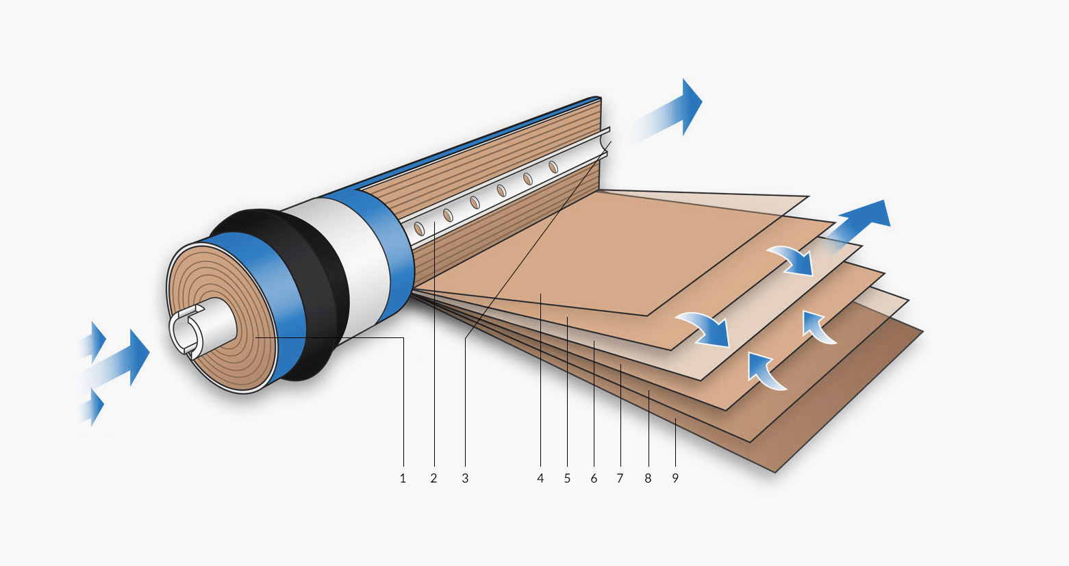 RO Membrane Exploded Diagram
- Feed in
- Product water collection tube (pure water outlet)
- Product water flow
- Spacer
- Membrane (filter)
- Product water carrier (transports the pure water to the centre)
- Membrane
- Spacer
- Outer casing
In the diagram above, we use the terms product water and concentrate. The product water is the very pure water that has been filtered through the RO membrane.